")

For differential pressure and flow
|
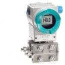
SITRANS P500 for differential pressure and flow |
||
|---|---|---|
|
Input |
||
|
Measured variable |
Differential pressure and flow |
|
|
Span (infinitely adjustable) |
Measuring span |
Maximum operating pressure |
|
1,25 ... 250 mbar |
160 bar (2320 psi) |
|
|
6,25 ... 1250 mbar |
||
|
Lower measuring limit |
||
|
100% of max. span and/or 30 mbar a (0.44 psi a) |
|
|
Upper measuring limit |
100% of max. span |
|
|
Start of scale |
Between measuring limits (infinitely adjustable) |
|
|
Output |
||
|
Output signal |
4 ... 20 mA |
|
|
3.55 mA, factory preset to 3.8 mA |
|
|
23 mA, factory setting 20.5 mA |
|
|
I pp ≤ 0.5 of max. output current |
|
|
0... 100 s in steps of 0.1 s, factory-set to 2 s |
|
|
3.55 ... 23 mA |
|
|
adjustable within limits:
|
|
|
Load |
||
|
R
B ≤ (UH - 10.5 V)/0.023 A in Ω, |
|
|
||
|
R B = 230 ... 1100 Ω |
|
|
R B = 230 ... 500 Ω |
|
|
Characteristic curve |
Linearly rising, linearly falling, square rooted characteristic rising, bidirectional square rooted characteristic and user-specific |
|
|
Measuring accuracy |
||
|
Reference conditions (in accordance with IEC 60770-1) |
|
|
|
||
|
Total accuracy |
||
|
Linear characteristic |
||
|
≤ 0,09 % |
|
|
≤ 0,11 % |
|
|
Square-rooted characteristic |
||
|
||
|
≤ 0,09 % |
|
|
≤ 0,11 % |
|
|
||
|
≤ 0,18 % |
|
|
≤ 0,22 % |
|
|
Conformity error at limit setting incl. hysteresis and reproducibility |
||
|
Linear characteristic |
||
|
≤ 0,04 % |
|
|
(0,003 . r + 0.01) % |
|
|
Square-rooted characteristic |
||
|
||
|
≤ 0,04 % |
|
|
(0,003 . r + 0.01) % |
|
|
||
|
≤ 0,08 % |
|
|
(r + 0.02 . 0,06) % |
|
|
Influence of ambient temperature per 28 °C |
(0,006 . r + 0.01) % /28% |
|
|
Influence of static pressure |
||
|
≤ 0.005 % per 70 bar |
|
|
≤ 0.03 % per 70 bar |
|
|
Step response time T63 without electrical damping |
≤ 90 ms |
|
|
Long-term stability |
≤ 0.1 · ) % per 5 years ≤ 0.15 · ) % per 10 years |
|
|
Influence of power supply |
≤ 0.005 ... 1 V |
|
|
Rated conditions |
|
|
|
Mounting position |
Any |
|
|
Ambient conditions |
||
|
||
|
-40 ... +85 °C (-40 ... +185 °F) |
|
|
-20 ... +85 °C (-4 ... +185 °F) |
|
|
-50 ... +90 °C (-58 ... +194 °F) |
|
|
Climatic class |
||
|
Relative humidity 0 … 100 % (condensation permissible) |
|
|
Degree of protection (to EN 60529) |
IP66/IP68 (with corresponding cable gland) |
|
|
Electromagnetic Compatibility |
||
|
Acc. to EN 61326 and NAMUR NE 21 |
|
|
Permissible pressures |
According to 97/23/EC pressure equipment directive |
|
|
Temperature of medium |
||
|
-40 ... +125 °C (-40 ... +257 °F) |
|
| |
(Notes that the process flanges will not admit a flow of medium of temperature > 100 °C.) |
|
|
Design |
||
|
Weight (without options) |
Approx. 3,3 kg (7.3 lb) |
|
|
Material of parts in contact with the medium |
||
|
Stainless steel, mat. no. 1.4404/316L |
|
|
|
|
|
Standard: Viton (FKM (FPM)) |
|
|
Material of parts not in contact with media |
||
|
Electronics housing |
|
|
|
Process connection screws |
Stainless steel |
|
|
Mounting bracket |
Steel or stainless steel |
|
|
Measuring cell filling |
Silicone oil |
|
|
Process connection |
¼-18 NPT female thread and flange connection with M10 to DIN 19213 or 7/16-20 UNF mounting thread to EN 61518 |
|
|
Electrical connection |
|
|
|
Displays and controls |
||
|
Keys |
3 for local programming directly on transmitter |
|
|
Digital display |
|
|
|
Auxiliary power supply |
||
|
Terminal voltage on transmitter |
|
|
|
Separate power supply |
||
|
Certificates and approvals |
||
|
Classification according to PED 97/23/EC |
||
|
For gases of fluid group 1 and liquids of fluid group 1; complies with requirements of article 3, paragraph 3 (sound engineering practice) |
|
|
Explosion protection |
||
|
Explosion protection for Europe (to ATEX) |
||
|
PTB 09 ATEX 2004 X |
|
|
Ex II 1/2 G Ex ia/ib IIC T4 |
|
|
-40 ... +85 °C (-40 ... +185 °F) |
|
|
To certified intrinsically-safe circuits with peak values: |
|
|
Li = 400µH |
|
|
Ci = 6 nF |
|
|
BVS 09 ATEX E 027 |
|
|
Ex II 1/2 G Ex d IIC T4/T6 |
|
|
-40 ... +85 °C (-40 ... +185 °F) temperature class T4; |
|
|
To circuits with values: Um = DC 10.5 ... 45 V |
|
|
PTB 09 ATEX 2004 X |
|
|
Ex II 1 D Ex iaD 20 T 120 °C |
|
|
-40 ... +85 °C (-40 ... +185 °F) |
|
|
120 °C (248 °F) |
|
|
To certified intrinsically-safe circuits with peak values: |
|
|
Li = 400µH |
|
|
Ci = 6 nF |
|
|
BVS 09 ATEX E 027 |
|
|
Ex II 2 D IP65 T 120 °C |
|
|
To circuits with values: UH = 10.5 ... 45 V DC; Pmax = 1.2 W |
|
|
PTB 09 ATEX 2004 X |
|
|
Ex II 3 G Ex nA II T4/T6 |
|
|
Um = 45 V DC |
|
|
Ui = 45 V |
|
|
Li = 400µH |
|
|
Ci = 6 nF |
|
|
Explosion protection for USA (to FM) |
||
|
Certificate of Compliance |
No. 3033013 |
|
|
XP CL I, DIV 1, GP ABCDEFG T4 / T6 CL I, Zone 0, AEx ia IIC T4 |
|
|
Ta = T4: -40 ... +85 °C (-40 ... +185 °F) |
|
|
According to "control drawing": |
|
|
NI CL I, DIV2, GP ABCD T4/T6 |
|
|
Ta = T4: -40 ... +85 °C (-40 ... +185 °F) |
|
|
According to "control drawing": |
|
|
Explosion protection for Canada (to C CSA US ) |
||
|
Certificate of Compliance |
No. 2280963 |
|
|
CL I, DIV 1, GP ABCD T4 /T6; |
|
|
Ta = T4: -40 ... +85 °C (-40 ... +185 °F) |
|
|
According to "control drawing": |
|
|
CL I, Ex ia/Ex ib IIC, T4 |
|
|
Ta = T4: -40 ... +85 °C (-40 ... +185 °F) |
|
|
Ui = 30 V, Ii = 100 mA, Pi = 750 mW, Ri = 300 Ω , Li = 400 µH, Ci = 6 nF |
|
|
CL I, DIV2, GP ABCD T4/T6 |
|
|
Ta = T4: -40 ... +85 °C (-40 ... +185 °F) |
|
|
According to "control drawing": |
|
|
According to "control drawing": |
|
|
HART communication |
|
|---|---|
|
Load with connection of |
|
|
R B = 230 ... 1100 Ω |
|
R B = 230 ... 500 Ω |
|
Cable |
2 wire shielded: ≤ 3.0 km (1.86 miles), |
|
Protocol |
HART Version 6.0 |
|
PC/laptop requirements |
IBM compatible, RAM > 32 Mb, |
|
Software for computer |
SIMATIC PDM 6.0 |